Vacuum Fluorescent Displays are probably one of the coolest displays of all time. Certainly one of the most popular of recent history. Developed in 1959 by Philips they have endured right through to modern times. You can even still find them in current consumer electronics.
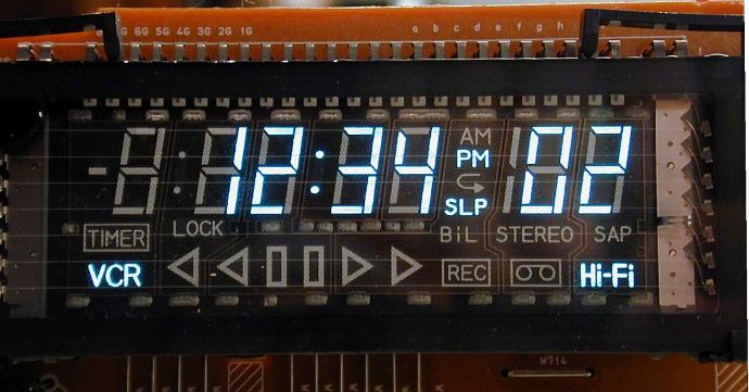
They have the great attributes of low power and high brightness, and they're easy to make with custom shapes in them. So they made it into almost every video recorder, DVD player, cooker, you name it.
The only problem with them is they need a little more voltage than the 5V that most Arduino users are used to working with to operate.
The basic idea with a VFD is you have a heated cathode coated with a special substance which emits electrons when hot. Those are attracted to, and collide with, phosphor coated anodes at a higher voltage than the cathode. Between the two you have a grid - a mesh of very fine wires - which either attracts (and lets through) the electrons, or repels them, depending on the voltage compared to the cathode voltage.
Fortunately for us the voltages involved aren't lethal, such as for instance with the Cathode Ray Tube, or the similar NIMO displays (if you don't know what a Nimo display is, and until a few days ago I'd never heard of them, I suggest you watch Fran Blanche's The NIMO Tube: Rarest And Most Dangerous Digital Display Of All Time YouTube video). That means it's reasonably safe (i.e., if we make a mistake it's only electronics we'll kill, not people) to work with them with an Arduino.
There are two tricky aspects to driving a VFD from an Ardiuno:
- The cathode filament requires an AC voltage, not DC.
- The anodes need to be tens of volts higher than the peak voltage of the cathode.
Neither of those can be provided by the Arduino.
Let's start with the cathode. Why does it need an AC voltage? Well, simply because the brightness of any segment is a function of the voltage difference between it and the cathode passing over it. With a pure DC voltage, one end of the cathode will be the DC voltage, and the other end will be 0V. So the segments at one end of the display will be brighter than at the other end. And we don't want that.
But there's a way with the Arduino that we can cheat. Really, all an AC voltage is, is a DC voltage that changes polarity regularly. Or that's how you can think of it in crude terms. And if you've read my "What Exactly is a GPIO Pin? article, a solution to this may already be presenting itself. It's quite simple:
Take a pair of IO pins, and set one HIGH and the other LOW. That creates a 5V difference between them
Swap the pins over so the HIGH one is now LOW and the LOW one is now HIGH. That reverses the voltage between them.
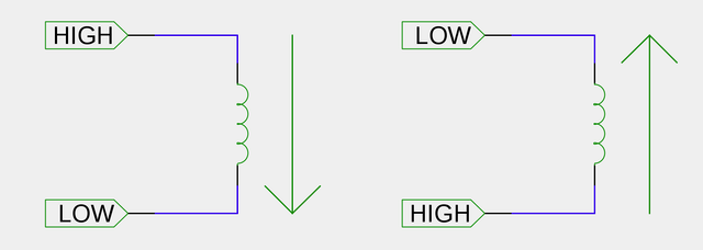
Do that fast enough, and you have a crude AC voltage. Neither end of the filament will be permanently LOW and neither end will be permanently HIGH. Crude, but effective.
The only thing you have to watch out for is the current consumption of the filament. If it's below 20mA at 5V then you can connect it directly to a pair of IO pins on the Arduino. The displays I have been working with take about 16mA, so they're fine. Anything more than about 20mA or so and you would need to consider other options. The simplest of which is to use a suitable H-bridge circuit (as you'd use for controlling a motor in two directions) that can work at 5V (tip: the L239D is not happy at just 5V. Find a MOSFET based alternative).
So now we have solved the cathode problem we can consider the anode and grid voltage problem. As I mentioned the anodes and grids have to be a voltage higher than the peak voltage of the cathode. That means a voltage higher than 5V. But what voltage? Well, I can't tell you that. Why? Simply because there ate too many variables.
Most non-trivial VFDs are multiplexed, in just the same way as many LED displays are. That means only one set of segments (we'll say a digit in this example, though they don't have to form digits, or even be in the same physical locality in a display) is illuminated at a time. Add to that the brightness of a segment is a function of the number of electrons that strike the phosphor coating, and you can begin to see the problem: the less time an anode + grid combination is active for, the less the quantity of electrons will strike the phosphor, and so the dimmer the segment will be. However, the number of electrons that get attracted to the anode is also a function of the voltage difference between the anode and cathode. Thus, the more digits you have in your display the higher the voltage difference you will need to have between cathode and anode in order to maintain a good brightness.
The displays I have been working with have 9 digits. That means that each digit is only active for 1/9th of the time. I found, through experimentation, that a grid/anode voltage of around 30V, which equates to a voltage difference of 25V, gave a good brightness to the display. At an anode voltage of around 12V (difference of 7V) the display was visible in the dark, but not by daylight. However, if I only illuminated one digit and didn't perform any multiplexing the display was perfectly visible in daylight at around 12V.
So you have to be prepared to control voltages in the order of 30V to run the display well. Those kind of voltages are fine for human consumption, but if they should ever touch your Arduino (e.g., from a loose hookup wire on your breadboard) you can kiss your Arduino goodbye. I did all my experimentation with a cheap Chinese clone that I didn't mind throwing away if I blew it up. You may want to do the same.
Fortunately, the currents involved in the high voltage portion are really really tiny. I mean, we're talking a few (well, a few billion) electrons here. My bench power supply couldn't even register the current for one segment. We're looking at nanoamps or even picoamps. Maybe even femtoamps. Really tiny amounts. So we don't need anything fancy to do the switching. Just a simple NPN transistor will do the job, as long as it is happy switching at least 30V (or whatever voltage you need to use for your display). To keep things simple with my display, since I needed 17 connections (8 for the segments and 9 for the grids) I chose to use the ULN2003 chips - 7 Darlington pairs per chip, which meant I just needed 3 chips instead of 17 transistors. Much neater on the breadboard.
Since we're wanting to turn power to the anodes and grids on and off we can't just put the transistor in series with the anode (or not easily, anyway). However, since we only want really tiny currents it's possible to provide it through a nice big resistor. That resistor can then be a pull-up resistor on what is effectively an Open Collector output. With the transistor off, the resistor pulls the voltage up, and with the transistor on the voltage is pulled down. A simple circuit:
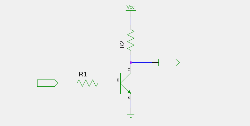
R1 is a simple base current limiting resistor. 1K should suffice. For R2 you need something that won't consume too much current when the transistor is turned on. I chose 10K since I have millions of them (and that's not an exaggeration) in my bits box. Vcc in the diagram above is your 30V supply, and of course, the ground is shared between that and your Arduino's ground.
The same circuit is used for both the anodes and the grids. Just multiply that up by the number of grid and anode connections.
Because of the inverting nature of this circuit (it's actually a NOT gate in Resistor-Transistor Logic) we need to set the IO pin LOW to turn the corresponding grid or anode on, and HIGH to turn it off.
So now an example program for the Arduino. This is for the 9 digit displays I have - you would need to adjust it for your displays.
// Pins for our grids and anodes
const uint8_t grids[9] = {13,12,11,10,9,8,7,6,5};
const uint8_t anodes[8] = {3, 4, A5, A4, A3, A2, A1, A0};

// This is how the digits are arranged
/*
 *     1
 *  128  2
 *     64
 *   32  4
 *     8
 *          16
 */

// And this is the corresponding number mappings.
// The numbers are provided twice, once without and once with
// the decimal point (so 0-9 and 0.-9.).
const uint8_t numbers[20] = {
    0b10101111,
    0b00000110,
    0b01101011,
    0b01001111,
    0b11000110,
    0b11001101,
    0b11101101,
    0b10000111,
    0b11101111,
    0b11001111,
    0b10111111,
    0b00010110,
    0b01111011,
    0b01011111,
    0b11010110,
    0b11011101,
    0b11111101,
    0b10010111,
    0b11111111,
    0b11011111
};

// Somewhere to store our value to display
uint8_t digits[9] = {1, 2, 3, 4, 5, 6, 7, 8, 9};

void setup() {
    // Set up the grids
    for (int i = 0; i < 9; i++) {
        pinMode(grids[i], OUTPUT);
        digitalWrite(grids[i], LOW);
    }
    // and anodes.
    for (int i = 0; i < 8; i++) {
        pinMode(anodes[i], OUTPUT);
        digitalWrite(anodes[i], LOW);
    }

    // These two are our cathodes.
    pinMode(1, OUTPUT);
    pinMode(2, OUTPUT);
}

void loop() {
    // Which phase is our cathode in right now?
    static bool phase = false;

    // Set the cathode pins to opposite states
    digitalWrite(1, phase);
    digitalWrite(2, !phase);

    // and flip the phase for next time.
    phase = !phase;

    // Put the value of millis one digit at a time into the display store
    uint32_t m = millis();
    digits[8] = m % 10; m /= 10;
    digits[7] = m % 10; m /= 10;
    digits[6] = m % 10; m /= 10;
    // We want a decimal point on this one, so add 10 to it.
    digits[5] = 10 + (m % 10); m /= 10;
    digits[4] = m % 10; m /= 10;
    digits[3] = m % 10; m /= 10;
    digits[2] = m % 10; m /= 10;
    digits[1] = m % 10; m /= 10;
    digits[0] = m % 10;

    // Update one digit of the display
    update();

}

// Every time this function is called the next digit is displayed.
// After all 9 have been displayed it goes back to the start.
void update() {
    static int8_t grid = 0;

    // Turn off all grids
    for (int i = 0; i < 9; i++) {
        digitalWrite(grids[i], HIGH);
    }

    // Turn on just the anodes we want for this digit
    for (int i = 0; i < 8; i++) {
        digitalWrite(anodes[i], numbers[digits[grid]] & (1 << i) ? LOW : HIGH);
    }

    // and turn on our grid.
    digitalWrite(grids[grid], LOW);

    // Move to the next grid ready for next time,
    grid++;

    // and loop if we need to.
    if (grid == 9) grid = 0;
}