Boards are now in stock. Normal production has resumed.

The smallest just got smaller
Our pulse rifle counter just keeps getting smaller and smaller, and better and better. It has now reached the limit on how small it can get.
We also have different variants to suit every pocket.
No Sound
£ 40 .00
- Basic counter with no sound
- Inputs for trigger and magazine
- Signal to control muzzle flash LED
With Amplified Sound
£ 70 .00
- Advanced counter with sound
- Inputs for trigger and magazine
- Signal to control muzzle flash LED
- 8W Class D amplifier
Also available with green or blue LEDs
To squeeze our pulse rifle counter board into an even smaller size we have changed the wiring method. Instead of individual JST PH connectors for each thing we now have one single integrated connection that contains all the connections in one plug.
Not only does this make the connector smaller, but it should also now be impossible to plug the wrong thing into the wrong place. However it does become slightly trickier to do the wiring in the first place.
The connector looks like this, and has 8 connections:
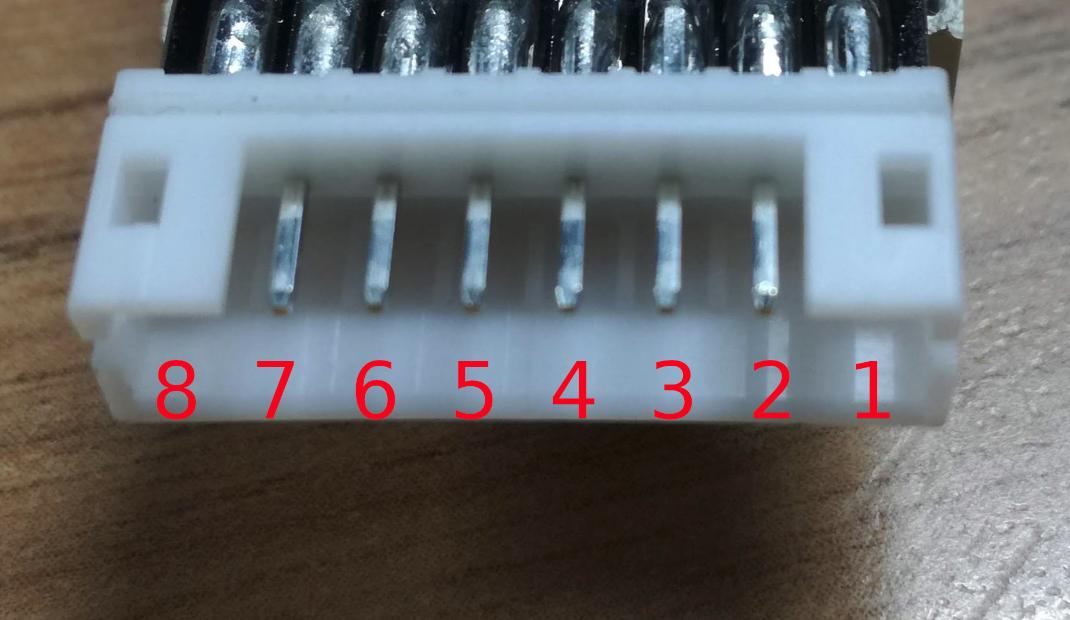
From right to left the pins are:
- Reset (this is part of the programming interface, you can ignore it)
- Power +
- Ground
- Speaker +
- Speaker -
- LED Output
- Magazine Input
- Trigger Input
You may notice that there is only one Ground connection. That single connection has to go to the battery and the switches for the magazine and trigger. If the LED driver is being powered by a different power source to the rest of the system then it should go to the ground of the LED driver as well.
Of course, it doesn't have to go right to that pin, just connect to something that is itself connected to that pin, such as the negative of the battery.
To make wiring easier we include a small wiring harness in the
package for you. The ground pin on this harness actually has two wires
going to it, one for the battery and the other for you to connect to
your buttons / switches:
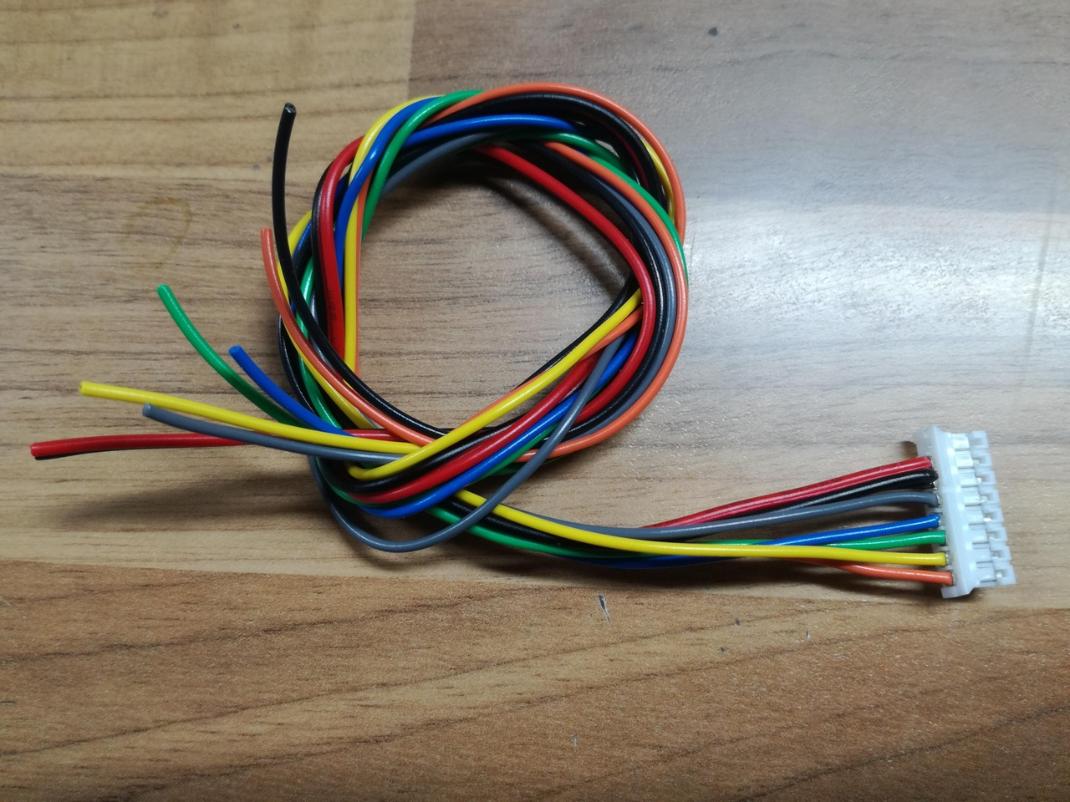
The wire colours are as follows:
- Orange: Trigger
- Yellow (or purple): Magazine
- Green: LED
- Blue: Speaker -
- Blue: Speaker +
- Black: Ground for both power- and switches
- Red: Power+ .
Here's a wiring diagram to show you how everything fits together:
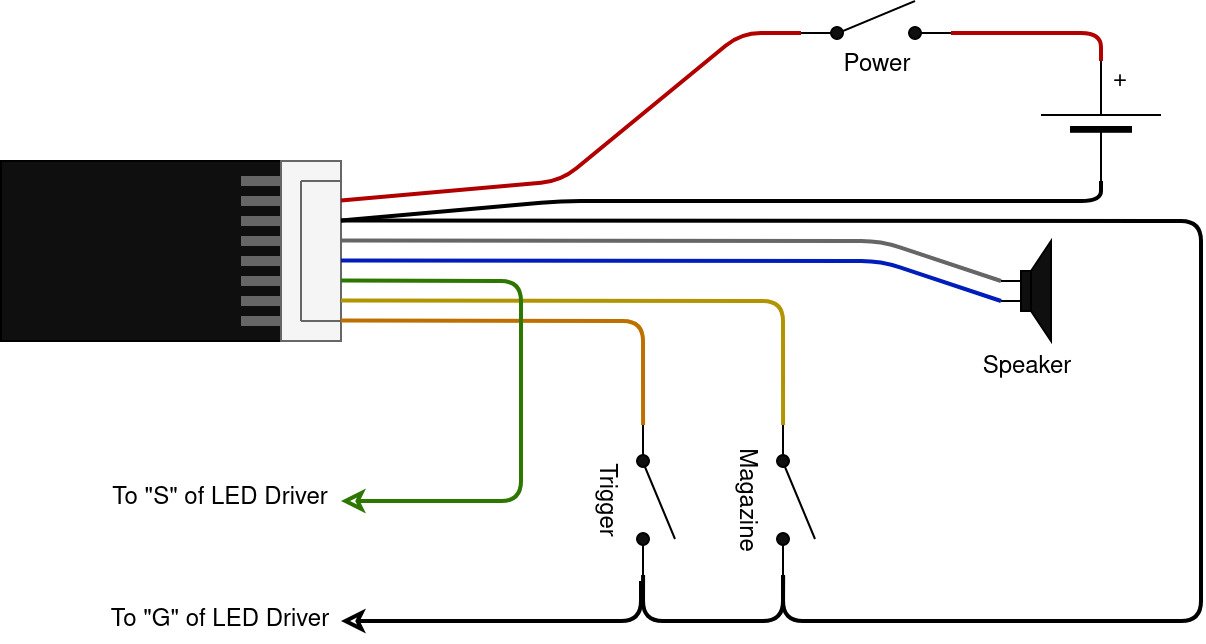
The connector is a 2mm pitch "JST PH" 8-pin. You can find them pre-wired (though with only one wire per pin) on eBay quite commonly if you want to create your own wiring.
If you don't have sound then just ignore the speaker - everything else is the same, except the ground wires are then split between two pins of the connector.
Which buttons and switches you choose to use is entirely up to you - no two builds are ever the same, so we are unable to recommend any specific switches. However it is important to understand the principle of operation so that you get the right type.
Both buttons should be of the "normally open" type. The magazine button has to be pressed in for the unit to operate. This is usually done by the magazine itself either pressing a physical button or using a magnet and reed switch.
If you get an LED driver and muzzle flash LED to complement your system this requires a separate feed from the battery to power it. The green wire goes to the signal "S" input of the driver. If the one battery powers both the counter and the LED driver then the "G" connection can be omitted as this is the same as the - connection from the battery.
Battery
Which battery you choose depends on which counter you have. The sound enabled variant requires a higher voltage than the no-sound variant, because of the built in amplifier. For the no-sound version I would recommend a single-cell Lithium Ion or Lithium Polymer battery. This gives a small size with a good power density at 3.4-4.2V which is ideal. The sound variant needs at least 5V, so a "2S" battery (that is, a 7.4V Li-Ion / Li-Poly battery) is best. You can power from higher voltages (15V is the max) so the existing battery in an Airsoft conversion could be used. Note, though, that the higher the voltage you provide the more power has to be thrown away by the voltage regulators, and so the hotter the unit will get. For higher voltages it could be beneficial to insert a small 5V "UBEC" (switching power regulator) to first drop the power down to a more manageable voltage.
Both batteries and UBECs can be obtained from most RC hobby stores. I have had good results with (although I am in no way affiliated with) HobbyKing.