People, all the time, use a simple resistor-based voltage divider to change 5v into 3.3v. You see it all over the place. For instance, when you want to get your 5V Arduino to communicate with a 3.3V ESP8266 - you use two resistors (10K and 22K say) to drop the 5V of the Arduino down to the 3.3V the ESP8266 expects.
And that is all fine and dandy.
However I all to often come across people attempting to do the same thing to power a 3.3V device off 5V. After all, if you can use it for changing 5V into 3.3V for the signals, surely the same thing works for the 5V power to 3.3V, right? I mean, it's the same 5V isn't it?
Well, no. You can't. Absolutely not. And it's all because of the current.
Let's go back to basics. Ohm's Law.
Ohm's law states that the current through a conductor between two points is directly proportional to the voltage across the two points. Introducing the constant of proportionality, the resistance, one arrives at the usual mathematical equation that describes this relationship:

Let's apply that to the basic voltage divider:
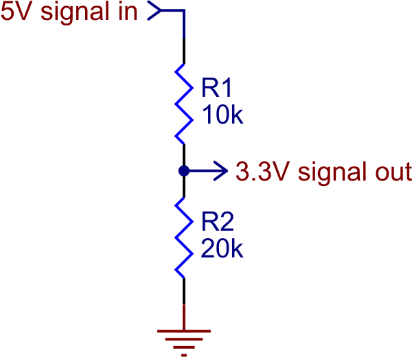
From basic principles we know that resistors in series are simply added together. So we can calculate the current that is flowing from 5V to Ground through the two resistors.
- I=V/R = 5 / (10000 + 20000)
That equals 166.666µA.
We can then swivel the formula around and look at what voltage is dropped across one of the resistors - say R1. If I=V/R then V=R×I.
- 10000 × 0.0001666 = 1.666V
So if 1.666V is dropped across R1 then the voltage at the mid node ("3.3V Signal Out") must be 5 - 1.666 = 3.333V. Which is correct.
And that is all fine. We have proved, with Ohm's Law, that the voltage divider works.
But there is one important thing missing from that schematic, and that is the item the 3.3V is going into. So let's add an ESP8266's 3.3V power pin to it. Now an ESP8266 can draw up to 300mA when transmitting. That means the "3.3V signal out" must have up to 300mA coming out of it at times. That current has to come from somewhere, and that somewhere is the 5V supply - via R1.
So through R1 there is now 300mA plus 166.666µA, or 300.166mA.
But surely the voltage dropped across that resistor is dependant on the current flowing through it, yes? After all, V=R×I, isn't it?
Absolutely. So let's calculate it.
- V = R×I = 10,000 × 0.300166 = 3001.66V
Whoah! Hang on there! How can three thousand volts be dropped across that resistor? There's only 5 available! Quite right. So 5 volts is all that can be dropped across the resistor, making it 0V at the 3.3V pin instead of 3.3V. On top of that the current that flows through it is limited by Ohm's Law: I=V/R, and V = 5V, R = 10000, so I=0.0005 or 500µA.
You see the problem here? The voltage at the output is completely dependent on the current being drawn through the output. As soon as you try to draw more than a few microamps out of the output the voltage drops. Draw more than a few hundred microamps and the voltage drops to nothing at all. Not only that the current that can possibly flow through there is severely curtailed.
And that is why you can't use resistors to do the job of a proper voltage regulator.