A lot of the time on the Arduino forums we get questions regarding wiring things together. One common format is:
I want to connect my 12V powered LED strip to my Arduino but I can't get it to communicate. I have checked all the connections and they seem fine. I have a 12V power supply for the LEDs and the Arduino is powered from the computer.
And 9 times out of 10 the first question we have to ask in return is:
Have you connected the grounds together?
And guess what the reply to that usually is? Yep:
No, do I need to? And isn't that dangerous, connecting a 12V ground to the 5V Arduno ground?
That in itself shows a fundamental lack of knowledge about what "ground" actually is. So let's start by clearing that up:
Ground, technically, is just a name given to a point in your circuit. That point is a point chosen by you against which all other voltages in the circuit are measured. Often it is the point of lowest potential, such as the - side of a battery, or the - connection of a power supply. Or it may have been chosen for you, such as the ground signal from the USB connection to your computer.
The 5V pin of the Arduino isn't actually 5V - it is 5V with respect to the ground pin. Equally you could rename the 5V pin to Ground, and what was the ground pin then becomes -5V with respect to [the new] ground.
So ground has to be a single point in your circuit against which all voltages "make sense".
Let's take a look at the typical circuit from the original question. An Arduino connected to some 12V device (such as some 12V LEDs):
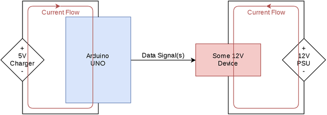
Here you can see the Arduino connected to, for example, a 5V USB charger. It could be a battery, or it could be the USB port on your computer. It matters not. Connected to that is a 12V device which then has its own 12V power supply. Now. Where is ground in that circuit?
The 5V pin of the Arduino is 5V with respect to the ground pin of the Arduino. So seen from the Arduino's point of view ground is, in the image above, the bottom line of the Arduino's power circuit (charger -). However, the 12V of the external circuit is 12V with respect to the - side of the 12V PSU. So seen from the point of view of the 12V device the ground is the lower side of the 12V circuit - the "PSU -" connection.
That doesn't sound too bad, does it? Each device's power is correct with respect to the power supply it is running off. As far as that goes, sure. However take a look at the data signal going from the Arduino to the 12V device. What voltage is that at?
Well, seen from the Arduino's point of view, with respect to it's ground, since it is generating the signal, it is a 5V signal. But, what about what the 12V device sees? What voltage is that signal with respect to the 12V circuit ground?
Given that voltages aren't absolute - they are only relative to a reference point within the same circuit, it is impossible to know what the voltage is there.
There's something more fundamental at play here though which can help you to understand it even better. In the image above there are two red arrows in loops. That is the flow of the current around the circuit (shown as conventional current flow). The key phrase there is around the circuit. Current has to flow out of a supply, through a circuit, and back to the supply from where it came.
In the circuit above the current can flow out of the 5V, through the Arduino, and back to the 5V again because there is a complete loop there. Likewise there is a loop from the 12V supply, through the 12V device, and back to the 12V supply again. But there is no such loop for the signal from the Arduino to the 12V device. If we think of the Arduino's output pin as a small power supply there really should be some way for the current to get out of the Arduino, through whatever it is connected to, and then back to the Arduino again. There is no way for that to happen in this circuit.
So you connect the grounds. As soon as you do that a lot of things start to happen. Let's do that now and see how the circuit looks:
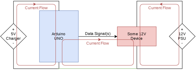
The grounds are now linked by the green wire at the bottom. Immediately we can now see a loop has appeared where the current from the IO pin can flow through the 12V device, out of the ground connection of the device, along the green wire, and back up through the ground connection of the Arduino.
In actuality the loop is a branch from the 5V power loop. Current goes from 5V into the Arduino where it splits, some to run the Arduino and some out of the IO pin. From there it goes through the 12V device, down to ground, then joins the current flowing out of the ground of the Arduino to go back to the 5V supply. It's useful to think in terms of discrete loops though so you can get a better idea of how the ground fits into things.
Also, now, since the ground of the 5V section and the ground of the 12V section are one and the same (in a schematic all points along a line are the same point) any signals generated from the 5V side are recognisable by the 12V side as 5V since the reference point (ground) is the same for every point in the circuit.
But isn't it dangerous?
Absolutely not. Not only is it not dangerous, it's safer than not connecting grounds together. Since now the whole circuit has a single baseline voltage to reference everything from 12V is 12V and 5V is 5V. Without that link the voltage difference between ground on the 5V side and 12V on the 12V side could potentially be many hundreds of volts (especially when the distances between the two points is great). For fully isolated systems, such as battery powered devices, that is not a problem. For anything using power supplies though it can be quite dangerous. And that leads me on to my next point - a slight variation on the question:
I built a circuit with a 12V device powered from a power supply which is controlled by my Arduino. It all works well. But as soon as I run the Arduino from a battery instead of my computer it stops working.
This is a classic case where the grounds haven't been connected together by the user, but there exists another path linking the grounds together. This is most often the earth connection of the computer and the earth connection of the power supply being linked together through the house wiring:
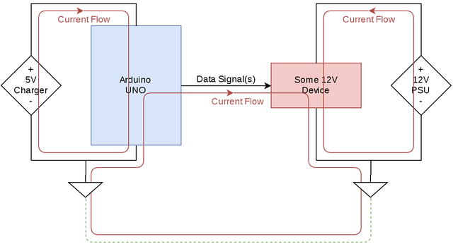
As you can see the current loop still exists, it just takes a longer route. As soon as you remove the Arduino from your computer and power it from batteries - or a power supply that has no connection to earth - the lower part of that loop disappears completely and you are back to the original circuit with only 2 loops. And it stops working.
Connect the grounds together manually, though, and you reinstate that portion of the loop, making it all work again.
So there you have it. If you have multiple power supplies in your project, whatever they may be (except in special circumstances) you must connect the grounds together for it to work. If it works without connecting the grounds together then you are inadvertently relying on some pre-existing ground connections to do the job for you, and that is likely to fail if your setup ever changes.