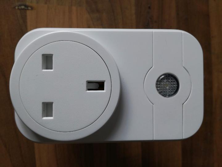
The SWA1 Smart WiFi sockets are great cheap WiFi controlled sockets that you can get on Amazon. Not only are they very convenient, but they are eminently hackable. Hackable to the extreme.
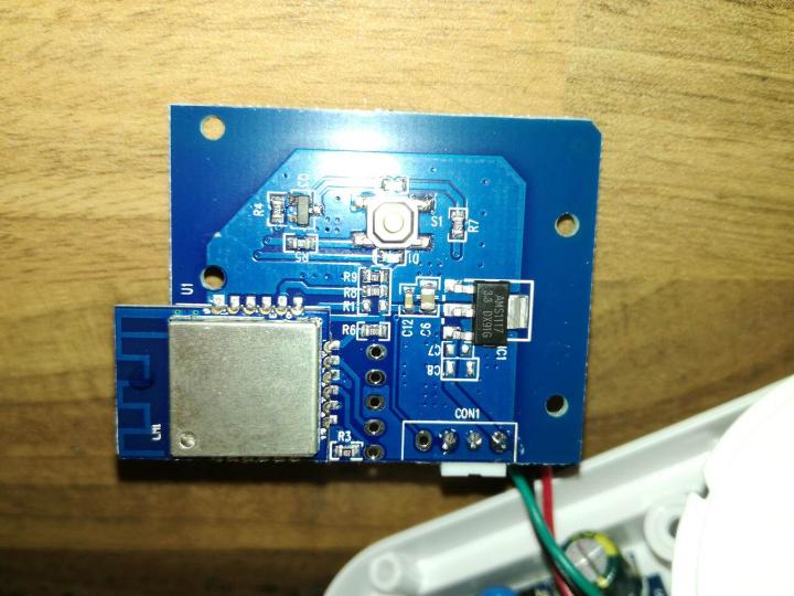
Inside one of these great little sockets you have two circuit boards. One is the power supply (5V) and the relay that switches the outlet on and off, and is really nicely designed and built. The other is the main control board. And I think you'll like what is on the other side of it.
There's not a lot to see on this board. Just a button, two LEDs, a 3.3V voltage regulator (the ubiquitous AMS1117) and a silver canned module. It's that silver canned module that is so interesting, though.
Although it doesn't look like any that you would normally find, it's actually an ESP8266 module. Just like you get on the NodeMCU, Wemos D1 boards, etc. And that means that we can reprogram it very easily using the ESP8266 plugin for the Arduino IDE or UECIDE.
To manage that, though, we need the UART pins, and GPIO0 to trigger bootloader mode. Fortunately, this board has those pins broken out to a handy 5-pin header:
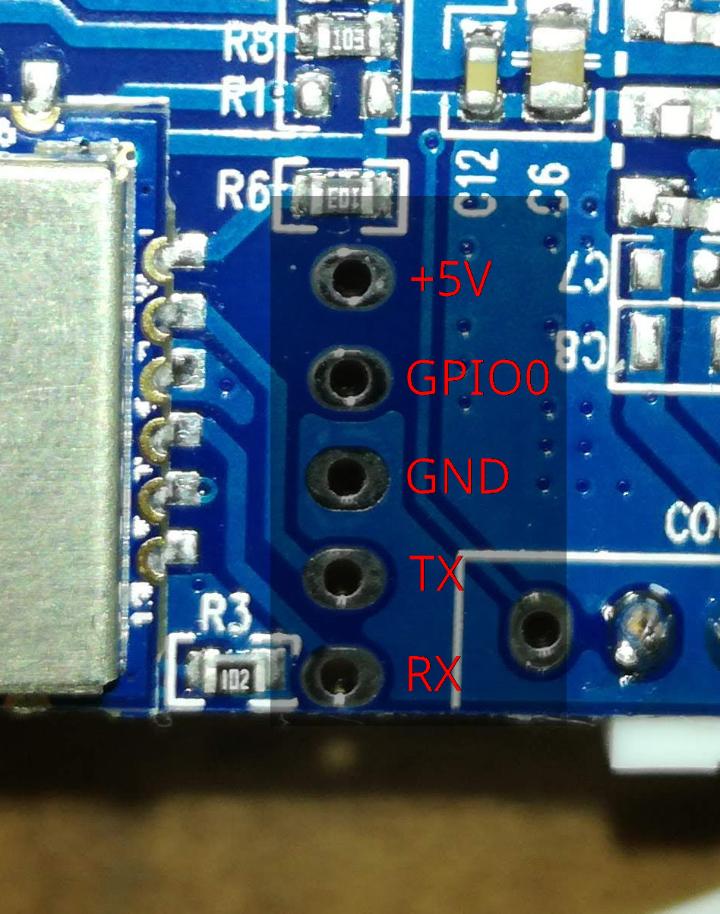
Connect GPIO0 to GND, wire TX, RX and GND up to a USB to UART adaptor (swapping TX to RX and RX to TX of course), and provide 5V/GND to the +5V/GND pins. You need to use an external power supply for two reasons. One is that the power supply connected to the 5V rail has lots of capacitance on it, and that causes most USB adaptors to "bounce" when the 5V is connected - that is, they get kicked off the USB then re-connect again. The second reason is that you need to be able to turn the power on and off at will.
Once it's all connected up, you can flash your own firmware. Just turn the power on a moment before upload is attempted so it's in the bootloader and away you go.
Of course, you'll need to know the proper settings for the module. You set it as a "Generic ESP8166 Module" in the IDE, and select the following settings:
- Flash Mode: DOUT
- Flash Frequency: 40MHz
- Flash Size: 1MB (No SPIFFS)
- Crystal Frequency: 26MHz
- CPU Frequency: 160MHz
- Reset Method: None
- Upload Speed: Whatever your UART adaptor can support reliably.
To write your own firmware you're going to need to know what GPIO does what, as well. So here they are:
- Button: GPIO13
- Blue LED: GPIO4
- Red LED + Relay: GPIO5
- Extra Pin: GPIO14
Here's the sketch I'm running on these sockets. It uses MQTT to communicate with my own Mosquitto broker, and I use MQTT Dash on Android to control it all. It also uses my DebouncedInput library and the popular PubSubClient library for Arduino/ESP8266.
// Flash mode: DOUT
// Flash Frequency: 40MHz
// Flash Size: 1MB (No SPIFFS)
// Reset method: None
// Crystal Frequency: 26MHz
// CPU frequency: 160MHz
// Upload speed: 921600

// Button: GPIO13
// Blue LED: GPIO4
// Red LED + Relay: GPIO5
// Extra Pin: GPIO14

#include <ESP8266WiFiMulti.h>
#include <ArduinoOTA.h>
#include <PubSubClient.h>
#include <DebouncedInput.h>

ESP8266WiFiMulti wifiMulti;
WiFiClient espClient;
PubSubClient client(espClient);

bool powerState = false;

#define NAME "NameOfTheDevice"
#define OTAPW "ChooseAPassword"
#define BROKERUSER "brokerusername"
#define BROKERPASS "brokerpassword"
#define SUBTOPIC "where/to/get/the/commands/from"
#define PUBTOPIC "where/to/publish/the/status/to"
#define POWERPIN 5
#define BUTTONPIN 13
#define LEDPIN 4

DebouncedInput button(BUTTONPIN, 10, true);

void callback(char *topic, byte *payload, unsigned int length) {
    if (!strcmp(topic, SUBTOPIC)) {
        if (!strncmp((char *)payload, "on", length)) {
            digitalWrite(POWERPIN, HIGH);
            powerState = true;
            client.publish(PUBTOPIC, "on", true);
        } else if (!strncmp((char *)payload, "off", length)) {
            digitalWrite(POWERPIN, LOW);
            powerState = false;
            client.publish(PUBTOPIC, "off", true);
        }
    }
}

void setup() {
    button.begin();

    WiFi.mode(WIFI_STA);

    pinMode(POWERPIN, OUTPUT);
    pinMode(LEDPIN, OUTPUT);
    digitalWrite(POWERPIN, LOW);
    digitalWrite(LEDPIN, LOW);

    client.setServer("your.mqtt.server", 1883);
    client.setCallback(callback);

    // Add more of these for access to more APs.
    wifiMulti.addAP("YourSSID", "YourWiFiPassword");

    ArduinoOTA.setHostname(NAME);
    ArduinoOTA.setPassword(OTAPW);
    ArduinoOTA.begin();
}

void loop() {
    static uint32_t ts = millis();
    ArduinoOTA.handle();
    client.loop();

    if (wifiMulti.run() != WL_CONNECTED) {
        delay(100);
    } else {
        if (!client.connected()) {
            delay(100);
            if (client.connect(NAME, BROKERUSER, BROKERPASS)) {
                client.subscribe(SUBTOPIC);
            }
        } else {
            if (millis() - ts >= 5000) {
                ts = millis();
                client.publish(PUBTOPIC, powerState ? "on" : "off", true);
            }
        }
    }

    if (button.changedTo(LOW)) {
        powerState = !powerState;
        digitalWrite(POWERPIN, powerState);
        if (client.connected()) {
            client.publish(PUBTOPIC, powerState ? "on" : "off", true);
        }
    }

    digitalWrite(LEDPIN, !client.connected());
}