I have just taken delivery of a batch of USB C 2A powerbank charger + boost circuits from a seller on AliExpress. China churns out millions of these circuits every year, so you'd think they'd be good at it by now.
Here's the module in question:
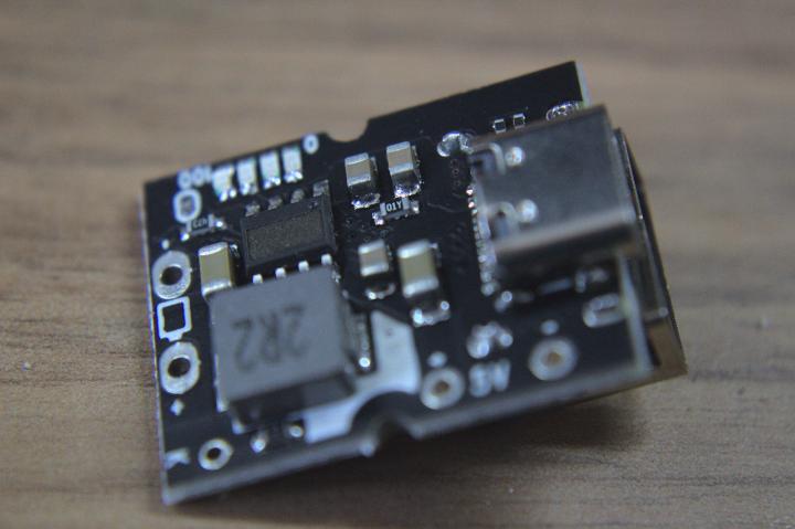
So long story short, I connect one of these up to a pack of 18650 cells that I have rescued from an old laptop battery. Connect the USB C port to a suitable power supply (through my trusty Keweisi USB power monitor) and everything appears to be good. It starts flashing an LED at me to say it's charging and < 25% charged, and the current and voltage levels from the power supply seem good.
I leave it charging for a while then go to see if I can get anything out of it.
Nup.
No such luck.
Probing around with my DMM makes me think that the 5V output pin isn't connected to anything. I can't find any continuity anywhere. So time to dig deeper.
Step one: remove all the components from one that I was messing with and managed to kill.
Step two: clean up any excess solder with some solder braid
Step three: rub the PCB all over with a coarse sand paper to remove all the solder mask, and hey presto. This is what we now have, and you can clearly see that there is no connection to the 5V pin:
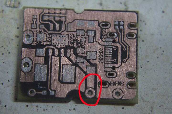
Oops? Still, that's an easy fix - a bit of wire from that pin (which also connects to the USB A on the other side of the board) and the 1206 capacitor just above it. And now I get power out!
But... only about 3V, which really is not right.
So now for even more digging. Looking around at videos from BigClive (you should check his channel out, especially if you like drunk Glasweigians) it looks like the chip (which they have handilly laser etched away the number on the top) is the good old IP5306 which has a recommended circuit of:
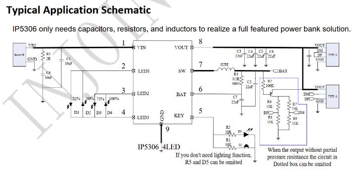
I can see most of that circuit laid out for me quite nicely in the PCB, but with notable exceptions:
There is no flashlight circuit
The "dotted box" (which isn't dotted) has been omitted, and most importantly:
R4 and C2 are missing
It's the lack of R2 that is most concerning. Without that the chip has no way of knowing what is going on with the battery. So time to do another little modification - the addition of a resistor. I don't have a 0.5 ohm one to hand, but I do have a 1 ohm one, which should do just as well. I can always put two in parallel if I really need to.
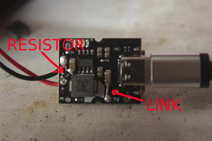
Et voila, suddenly I get 5V out. The chip is now boosting the voltage properly and it works!
These modules, which are from a seller called "TZT Official Store", are obviously some reject or prototype that went wrong, and should really not be being sold by them. But if you have been duped into buying any from them all is not lost - these two small modifications should get them out of the rubbish bin and back into something useful.
Addendum
It seems all I can get from these "2A" modules is 1.5A max. Pretty
poor really. Even after adding a second 1 ohm resistor to take it to the
recommended 0.5 ohm, and adding the missing capacitor across the
battery (C2 in the schematic). And then the inductor on the board gets
rather hot. Maybe it's time to upgrade that inductor to something a
little bigger.