Today's ESP8266 hack is another rather easy one. This time it's a very cheap LED RGB strip driver from Amazon. Well, I say ESP8266. In fact this one uses the ESP8285, which is basically an ESP8266 with 1MB of flash built in, so no need for an external flash chip. That makes it even cheaper to manufacture, and hence for you and I to buy. The ESP8285 is simply an ESP8266 with built-in flash memory. This both reduces cost and size, and is absolutely perfect for when you need to make something small and cheap but you don't really need that much flash space. The size, you see, is limited to 2MB (for the H16 variant - 1MB for the H08 variant).
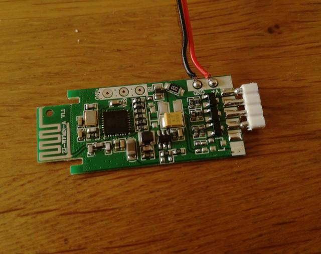
As you can see there's not a huge amount in this unit. And why should there be? With a chip as capable and integrated as the ESP8285 you don't need to add much to it to create an entire product. The ESP8285 of course is over on the left with the few support components that it needs (mostly for the antenna). In the centre is a small 3.3V switching regulator, and over to the right are a set of N-channel MOSFETs which are used to drive the LED strip. However there are a couple of little surprises there if you know just what to look for. For a start, let's take a closer look at those MOSFETs, shall we?
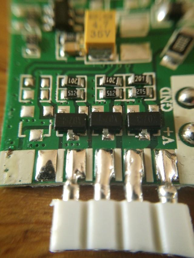
That looks very much like there's room for four MOSFETs. This particular board is sold as a 3-channel system for RGB strips. There's an RGBW variant for more money if you want it. It looks, to me, like the only difference is that the RGBW one has an extra MOSFET fitted in that left hand position, and a 5-pin connector soldered on. Upgrading this to RGBW will be an absolute doddle. Just slap in another MOSFET and two resistors (they used a 5.1kΩ pulldown and a 200Ω inline resistor. The actual values don't matter that much. 10kΩ pulldown and 100Ω inline would do fine). I'm going to use the TSM2314CX just because I happen to have them, and they're rated at 4.9A. I have no idea what the ones on the board already are, so I will probably replace those three as well so that we have a fully matched set.
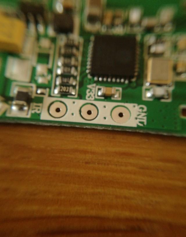
Another little surprise is a connection point on one side. This looks very much like it is designed to take an infra-red receiver module. I guess there's an IR controlled version of this unit available too. That connector could be useful.
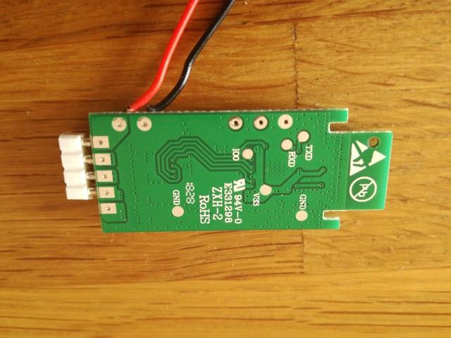
Now, as far as actually hacking goes, you may have noticed that there doesn't seem to be much in the way of connections for the UART. But that's because I haven't shown them to you yet. It's almost as if these manufacturers want us to hack these devices. They have stopped trying to even pretend they're not hackable. If you flip the board over and look at the underside, lo and behold, there are the UART and IO0 connections laid out for us. It couldn't be easier for us to wire up a UART adaptor and get programming. Well, it could be easier - they could have provided a real connector for us. But these pads will do instead. The reason they used pads instead of a connector is so that the board can be placed into a test jig with "Pogo pins" which connect with these pads. The whole programming and testing process can then be automated in the factory which again reduces costs.
I mean, do I really need to say anything more? You can treat the ESP8285 the same as an ESP8266 with 1MB flash. I used these settings and it worked perfectly:
- CPU Frequency = 80
- Crystal Frequency = 26
- Flash Frequency = 40
- Flash Mode = dout
- Flash Size = 1M (No SPIFFS)
Now as far as the IO pin assignments go that is very easy:
| Function | GPIO |
|---|---|
| Red | GPIO13 |
| Green | GPIO12 |
| Blue | GPIO15 |
| White | GPIO5 |
| IR | GPIO4 |
Note that there is a bug in earlier versions of the ESP8266 core for Arduino. analogWrite() likes to randomly lock the system up. That has been fixed in version 2.4.2 of the core, so make sure you are using that - otherwise you will have all sorts of issues.